



CNC Rebar Cage Rolling And Welding Machine

CNC Rebar Cage Rolling And Welding Machine suppliers

CNC Rebar Cage Rolling And Welding Machine factory

CNC Rebar Cage Rolling And Welding Machine best

CNC Rebar Cage Rolling And Welding Machine high quality

CNC Rebar Cage Rolling And Welding Machine price

CNC Rebar Cage Rolling And Welding Machine best

CNC Rebar Cage Rolling And Welding Machine best
CNC Rebar Cage Rolling and Welding Machine
1: Main Rebar Feeding Mechanism/ 1 set/ 12m length
2: Rotating Distributing Mechanism/ 1 set/ Max. single section: 13m
SJG2000 Automated Rebar Cage Rolling Welding Machine
Configuration List
|
No. |
Component Name |
Quantity |
Remarks |
|
1 |
Main Rebar Feeding Mechanism |
1 set |
12m length |
|
2 |
Rotating Distributing Mechanism |
1 set |
Max. single section: 13m |
|
3 |
Ring Template Rotating Mechanism A (Fixed Side) |
1 set |
For pile diameter ≤ 2m |
|
4 |
Ring Template Rotating Mechanism B (Moving Side) |
1 set |
For pile diameter ≤ 2m |
|
5 |
Hydraulic Automatic Support Device |
1 set |
|
|
6 |
Hydraulic Station |
1 set |
|
|
7 |
Electrical Control System |
1 set |
Inverter × 3, PLC × 1 |
|
8 |
Coiled Rebar Pay-off Frame |
1 set |
Load capacity: 2 tons |
|
9 |
Ring Template & Conduit |
2 sets |
Custom-made per drawings |
|
10 |
Random Tools & Accessories |
1 set |
|
|
11 |
CO₂ Shielded Welding Machine |
1 unit |
Special matching |
|
12 |
Transportation |
Included |
Technical Parameters
|
Parameter |
Specification |
|
Cage Diameter Range |
800–2000 mm |
|
Max. Cage Length |
12 m |
|
Spiral Rebar Diameter |
ø5.0–16.0 mm |
|
Main Rebar Diameter |
ø12.0–32.0 mm |
|
Spiral Rebar Spacing |
50–500 mm (Stepless Adjustable) |
|
Hydraulic System Pressure |
10 MPa |
|
Max. Installed Power |
20 kW, 380V/50Hz/3Phase |
|
Operating Temperature |
0–40°C |
|
Operating Time |
24 hours/day |
|
Floor Space |
30 m (L) × 6 m (W) × 2 m (H) |
|
Machine Weight |
Approx. 20 tons |
|
Welding Method |
CO₂ Shielded Welding |
|
Welding Materials |
Welding wire, electrode |
Random Tools List
|
No. |
Tool Name |
Model |
Quantity |
Remarks |
|
1 |
Jack |
3T |
1 set |
Universal |
|
2 |
Hex Key Wrench |
– |
1 set |
Universal |
|
3 |
Adjustable Wrench |
12-inch |
1 set |
Universal |
|
4 |
Electric Wrench |
– |
1 set |
Universal |
|
5 |
Screwdriver |
– |
1 set |
Universal |
|
6 |
Special Wrench |
M36 |
1 set |
Special |
Step 1: Main Rebar Loading
Pre-cut the main rebars to the required length as per the drawings, then connect them by butt welding or couplers. Subsequently, hoist and place the rebars onto the main rebar storage rack of the CNC Rebar Cage Rolling and Welding Machine for standby use.
The main rebar storage rack of this CNC Rebar Cage Rolling and Welding Machine is suitable for storing rebars with lengths ranging from 2 meters to 12 meters. The entire rack is assembled by welding H-shaped steel and adopts a segmented structure with intervals of 2 meters per segment, facilitating disassembly, assembly, and transportation of the CNC Rebar Cage Rolling and Welding Machine.
Step 2: Coiled Rebar Loading
Hoist the coiled rebar and place it onto the pay-off frame of the CNC Rebar Cage Rolling and Welding Machine. The frame has a maximum load capacity of 2 tons and a height of 1.7 meters. The inner diameter of the upright columns can be customized to be telescopic to accommodate different material specifications in the CNC Rebar Cage Rolling and Welding Machine.

Step 3: Main Rebar Threading and Clamping

Workers distribute the main rebars evenly around the circumference of the distributing disc. The rebars are then threaded through the conduits of both the fixed and movable ring templates, and securely clamped using bolts within the conduits of the movable disc.
The distributing disc system consists of 6 distributing discs connected to the fixed disc and rotates synchronously with it. Rollers at the ends help reduce rotational resistance.
During clamping, ensure that the staggered length of each main rebar is maintained, typically around 1 meter.
Step 4: Coiled Rebar Threading and Winding Fixation

Pass the coiled rebar through the straightening mechanism until it crosses with the main rebars, then weld it firmly in place.

Step 5: Welding and Forming

Initial Welding:
At the head of the rebar cage, both the fixed and movable discs rotate synchronously, winding the coiled rebar around the main rebars for several consecutive loops. The coiled rebar is then securely welded to the main rebars.
Formal Welding:
The fixed and movable discs continue to rotate synchronously while the movable disc advances simultaneously. This causes the coiled rebar to automatically wind around the main rebars, with welding performed concurrently, thereby forming the rebar cage product.
Termination Welding:
At the tail of the rebar cage, both discs continue rotating while welding is temporarily paused. The coiled rebar is wound around for several additional loops, and its end is then welded and fixed to the main rebars to complete the welding process.
Welding Method:
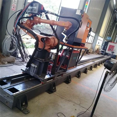
CO₂ shielded welding is commonly used domestically, offering minimal slag and high welding quality. Alternatively, an automatic welding robot can be selected (at an additional cost), with a maximum welding speed of 40–60 points per minute.
Step 6: Rebar Cage Separation from Rotating Discs

Cut the spiral binding wire;Move the movable disc forward to separate the rebar cage from the fixed disc;Loosen the bolts securing the main rebars in the template conduits of the movable disc;Move the movable disc further forward to completely separate the rebar cage from the movable disc.
Equipped with an electric wrench for lightweight and fast operation, improving work efficiency.
Step 7: Unloading the Cage and Lowering Hydraulic Supports

The finished rebar cage is unloaded using an overhead crane or by manually rolling it off the platform.
Throughout the welding process, to prevent deformation of the rebar cage due to its own weight, three hydraulic support devices are equipped to provide stable and adjustable support.
The specially designed hydraulic station utilizes commonly available domestic hydraulic components, ensuring long-lasting durability and high interchangeability for easy maintenance and replacement.
Step 8: Movable Disc Reset – Prepare for Next Cycle

After unloading the cage, reset the movable disc to its initial position to prepare for the production of the next cage.
The electrical control system utilizes imported PLC and touchscreen components from world-leading brands, further ensuring stable, reliable, and durable equipment performance.
Operations such as adjusting welding speed, modifying spiral reinforcement spacing, and changing the number of spiral reinforcement strands can be easily set directly on the touchscreen without the need for mechanical adjustments or stopping the machine. The system is user-friendly and easy to learn.
The system includes data storage functionality and supports user permission settings with password-protected access, ensuring specialized operation by authorized personnel.
This machine's control system has been practically applied in the domestic market for over five years, demonstrating maturity and stability. It also represents one of the company's key competitive advantages compared to other industry players.
Step 9: Adding Internal Stirrups

Specially matched for this process, ensuring stable and durable performance.
Internal stirrups are pre-bent to the required shape, supporting reinforcement bar diameters of 16–28 mm and stirrup diameters ranging from 300 mm to 2500 mm.
After the rebar cage is unloaded, workers manually position the internal stirrups inside the cage and tack-weld them in place. This provides enhanced support and prevents deformation of the cage structure.
Step 10: Finished Product

Mechanically produced rebar cages feature uniform appearance, even spacing, tight winding, and high concentricity, making them highly likely to pass inspections by owners and supervisors.
Hot Tags: cnc rebar cage rolling and welding machine, China cnc rebar cage rolling and welding machine manufacturers, factory, CNC Rebar Hoop Bending Machine, cnc steel bar processing equipment, Fully Automatic Mesh Welding Production Line, CNC Rebar Bending Center, Rebar bending center, CNC Rebar Shearing Production Line
Previous
No InformationYou Might Also Like



Send Inquiry